Replay of a software-in-the-loop run in an irregular sea (significant wave height 0.15 m). Heave and pitch are drawn three times larger than simulated. White hull: true state. Orange outline: the controller's estimate. Vertical line at the bow: the ultrasonic measurement. Dashed line: target height.
The question
A fully submerged foil gives almost the same lift at any depth. Thus the boat has almost no ride-height stiffness: linearised at 7 m/s it is unstable and close to a double integrator in heave. The boat has four states and three sensors: an ultrasonic height sensor at the bow, an attitude unit for pitch and a gyro for pitch rate. The height sensor measures the distance to the water, so the waves are in the measurement. I asked two questions:
- EstimationHow must an observer treat a height signal that contains the water surface?
- ImplementationDoes the controller still work when it runs as a separate program at 50 Hz, with a computation delay and real timing?
Setup
- BoatThe parameters of the Técnico Solar Boat SR02 (215 kg with pilot), from the MSc thesis of B. J. Belime (2020). Two front foils move together; I assume that the rear foil is also actuated.
- ModelNonlinear heave and pitch equations from first principles, with the loss of lift near the free surface, stall, actuator position and rate limits, servo lag and sensor noise. The trim agrees with the thesis within about 0.1° from 6 to 10 m/s.
- WavesLinear head waves: a regular wave of 5 cm amplitude, and irregular seas from a JONSWAP spectrum (significant height 0.10 to 0.25 m).
- ControllerLQR state feedback with integral action on the estimated height and the measured pitch, a reference prefilter and anti-windup. The observer is a Kalman filter with one extra state for a constant vertical force, which is what a speed or mass error does to the boat. The wave surface in the height reading is modelled as narrow-band noise at the encounter frequency.
- ImplementationDirect digital design at 50 Hz with a one-sample computation delay. The same model is built in MATLAB and in Simulink; they agree to 0.33 mm in closed loop.
Part I: the observer
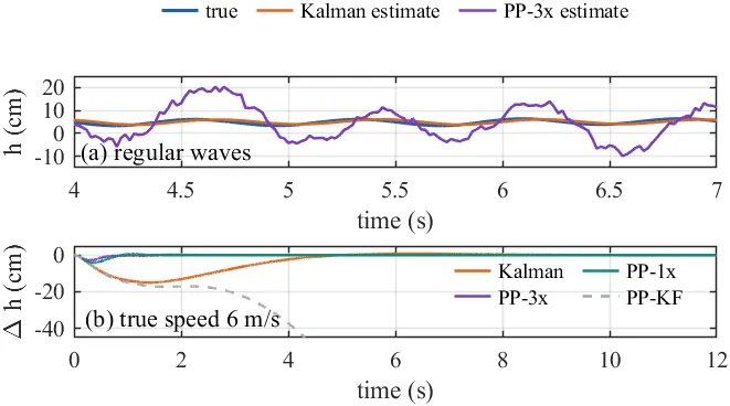
(a) Heave estimate in the regular wave. (b) Height deviation from the nominal response when the true speed is 6 m/s instead of 7 m/s. PP-3x and PP-1x place the observer poles at 3 and 1 times the controller poles; PP-KF places them at the poles of the Kalman filter.
- The usual rule places the observer poles two to five times faster than the controller poles. Such an observer recovers from a speed error ten times sooner, but it builds its heave estimate from the bow reading and follows the water surface. The height error in waves is four times larger (4.3 cm against 1.0 cm rms), and the foils move at their 20°/s rate limit most of the time.
- Pole locations alone do not define the observer. With the poles at exactly the Kalman filter’s locations, the different gain matrix weights the sensors differently: the foils chatter in waves, and a speed error drives the hull into the water.
- The Kalman filter meets the requirements. Its cost is a slow recovery from model errors: a speed 1 m/s too low gives a 15 cm transient that returns within 5 mm after 7.6 s.
Part II: the controller as a separate process
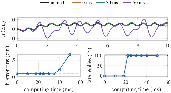
The controller runs in a second MATLAB process and exchanges data with the Simulink model over TCP, in real time. Top: height with three computing times. Bottom: height error and share of late replies against computing time.
- In lockstep, the trajectory with the external controller is identical to the in-model controller: the difference is exactly zero.
- In real time, nothing changes up to 18 ms of computing time. From 22 to 35 ms every reply is one sample late, but the height error stays at 0.94–0.99 cm. At 40 ms the error doubles, and at 50 ms the boat oscillates by ±10 cm. A linear analysis agrees: the damping ratio of a 2 Hz mode falls from 0.62 to 0.32, 0.11 and −0.03 for zero to three extra samples of delay.
- MATLAB’s
tcpclientwaits for the 15.6 ms Windows timer on each read and write, so a round trip took 31 ms, more than the control period. With Java sockets it takes about 0.2 ms.
Results
On the nonlinear model with actuator limits and sensor noise: a 5 cm height step settles in 2.2 s without overshoot; in the regular wave the height error is 0.99 cm rms and the pitch 0.33° rms; in irregular seas the error is 0.7–0.8, 1.8–2.2 and 3.6–4.9 cm rms for significant heights of 0.10, 0.15 and 0.25 m. Speed errors of ±1 m/s and mass errors of ±20 kg leave no steady-state error.
What this is not
This is a simulation study. Lift is quasi-steady, the waves are linear and come from ahead, and roll is not modelled. The chord, the foil depth, the sensor noise and the actuator rate are estimates. Both processes of the software-in-the-loop test run on one computer, so the delay of a real bus and the drift between two clocks are not in the test. This was a course project for ELEC9304 Control at the University of Sydney, submitted with Hengfei Xu.